
| Version 15 (modified by , 19 years ago) ( diff ) |
|---|
Writing efficient TLM-T SystemC simulation models for SoCLib
Authors : Alain Greiner, François Pécheux, Emmanuel Viaud, Nicolas Pouillon
A) Introduction
This document describes the modeling rules for writing TLM-T SystemC simulation models for SoCLib. Those rules enforce the PDES (Parallel Discrete Event Simulation) principles. Each PDES process involved in the simulation has is own, local time, and processes synchronize through timed messages. Models complying with those rules can be used with the "standard" OSCI simulation engine (SystemC 2.x), but can be used also with others simulation engines, especially distributed, parallelized simulation engines.
Besides you may also want to follow the general SoCLib rules.
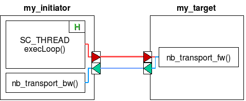
B) Single VCI initiator and single VCI target
Figure 1 presents a minimal system containing one single initiator, and one single target. In the proposed example, the initiator module doesn't contains any parallelism, and can be modeled by a single SC_THREAD, describing a single PDES process. The activity of the my_initiator module is described by the SC_THREAD execLoop(), that contain an infinite loop. The variable m_time represents the PDES process local time.
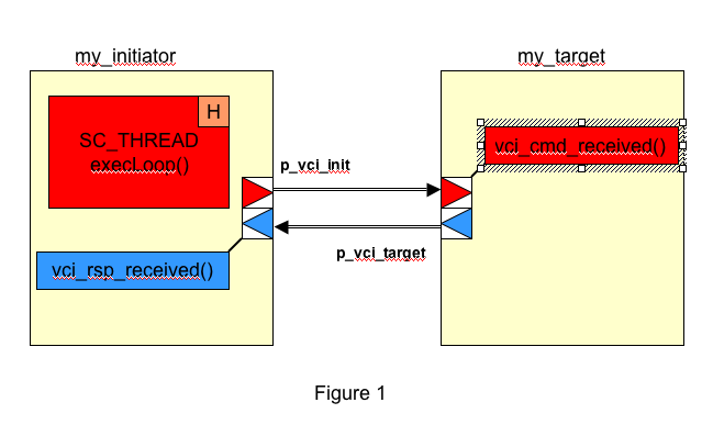
Contrary to the initiator, the target module has a purely reactive behaviour. There is no need to use a SC_THREAD to describe the target behaviour : A simple method is enough.
The VCI communication channel is a point-to-point bi-directionnal channel, encapsulating two separated uni-directionnal channels : one to transmit the VCI command packet, one to transmit the VCI response packet.
C) VCI initiator Modeling
In the proposed example, the initiator module is modeled by the my_initiator class. This class inherit the BaseModule class, that is the basis for all TLM-T modules. As there is only one thread in this module, there is only one member variable time of type tlmt_time. This object can be accessed through the getTime(), addTime() and setTime() methods.
The execLoop() method, describing the initiator activity must be declared as a member function of the my_initiator class.
Finally, the class my_initiator must contain a member variable p_vci, of type VciInitiatorPort. This object has a template parameter <vci_param> defining the widths of the VCI ADRESS & DATA fields.
C.1) Sending a VCI command packet
To send a VCI command packet, the execLoop() method must use the cmdSend() method, that is a member function of the p_vci port. The prototype is the following:
void cmdSend(vci_cmd_t 	*cmd,	// VCI command packet
                   sc_time time);	// initiator local time
The informations transported by a VCI command packet are defined below:
class vci_cmd_t {
vci_param::vci_command_t  cmd;  // VCI transaction type
vci_param::vci_address_t  *address;  // pointer to an array of addresses on the target side
uint32_t  *be;  // pointer to an array of byte_enable signals
bool   contig;	  // contiguous addresses (when true)
vci_param::vci_data_t  *buf;  // pointer to the local buffer on the initiator
uint32_t  length;  // number of words in the packet
bool  eop;  // end of packet marker
uint32_t  srcid;  // SRCID VCI
uint32_t  trdid;  // TRDID VCI
uint32_t  pktid;  // PKTID VCI
}
The possible values for the cmd fied are VCI_CMD_READ, VCI_CMD_WRITE, VCI_CMD_READLINKED, and VCI_CMD_STORECONDITIONAL Le champ address contient un ensemble d’adresses valides dans l’espace mémoire partagé du système modélisé. The contig field can be used for optimisation.
The cmdSend() function is non-blocking. To implement a blocking transaction (such as a cache line read, where the processor is frozen during the VCI transaction), the model designer must use the wait() method, that is a member function of the VciInitiatorPort class. The execLoop() thread is suspended. It will be activated when the response packet is received by the notify() method, that is also a member function of the VciInitiatorPort.
C.2) Receiving a VCI response packet
To receive a VCI response packet, a call-back function must be defined as a member function of the class my_initiator. This call-back function (named rspReceived() in the example), will be executed each time a VCI response packet is received on the p_vci port. The function name is not constrained, but the arguments must respect the following prototype:
void  rspReceived(vci_rsp_t  *rsp,
               sc_time  time)
The informations transported by a VCI command packet are defined below:
class vci_rsp_t {
vci_command_t  cmd;  // VCI transaction type
uint32_t  length;  // number of words in the packet
bool  eop;  // end of packet marker
uint32_t  srcid;  // SRCID VCI
uint32_t  trdid;  // TRDID VCI
uint32_t  pktid;  // PKTID VCI
}
The actions executed by the call-back function depend on the transaction type (cmd field), as well as the pktid and trdid fields. In the proposed example :
- In case of of a blocking read , the call-back function updates the local time, and activates the suspended thread.
- In case of a non-blocking write, the call-back function does nothing.
C.3) Initiator Constructor
The constructor of the classmy_initiator must initialize all the member variables, including the p_vci port. The rspReceived() call-back function being executed in the context of the thread sending the response packet, a link between the p_vci port and the call-back function must be established. Moreover, the p_vci port must contain a pointer to the initiator local time. The VciInitiatorPort constructor must be called with the following arguments:
p_vci(“vci”, this, &my_initiator::rspReceived, &m_time);
C.4) Lookahead parameter
The SystemC simulation engine behaves as a cooperative, non-preemptive multi-tasks system. Any thread in the system must stop execution after a given time, in order to allow the other threds to execute. With the proposed approach, a TLM-T initiator will never stop if it does not execute blocking communication (such as a processor that has all code and data in the L1 caches). This can block the simulation.
To solve this problem, it is necessary to define - for each initiator module- a lookahead parameter. This parameter defines the maximum number of cycles that can be executed by the thread before it stops. The lookahead parameter allows the system designer to bound the de-synchronization between threads. A small value for this parameter result in a better timing accuracy for the simulation, but implies a larger number of context switch, and a slower simulation speed.
C.4) VCI initiator example
template <typename vci_param>
class my_initiator : Tlmt::BaseModule {
public:
    VciInitiatorPort <vci_param>  p_vci;

    //////// constructor
    my_initiator (sc_module_name name,
                         uint32_t initiatorIndex
                         uint32_t lookahead) :
    p_vci(“vci”, this, &my_initiator::rspReceived, &m_time),
    BaseModule(name),
    m_time(0),
    {
    m_index = InitiatorIndex;
    m_lookahed = lookahead;
    m_counter = 0;
    SC_THREAD(execLoop);
    } // end constructor

private:
    tlmt_Time m_time;		// local clock
    uint32_t m_index;		// initiator index
    uint32_t m_counter;	// iteration counter
    uint32_t m_lookahed;	// lookahead value
    vci_param::data_t m_data[8];	// local buffer
    vci_cmd_t	m_cmd;		// paquet VCI commande

    //////// thread
    void execLoop()
    {
    while(1) {
        …
        m_cmd.cmd = VCI_CMD_READ;
        p_vci.cmdSend(&m_cmd, m_time.getTime()); 	// lecture bloquante
        p_vci.wait();
        …
        m_cmd.cmd = VCI_CMD_WRITE;
        p_vci.send(VCI_CMD_WRITE,…);
        p_vci.cmdSend(&m_cmd, m_time.getTime()); 	// écriture non bloquante
        ...
        // lookahead management
        m_counter++ ;
        if (m_counter >= m_lookahead) {
            m_counter = 0 ;
            wait(SC_ZERO_TIME) ;
        } // end if
        m_time.addtime(1) ;
        } // end while
    } // end execLoop()

    //////////////// call-back function
    void  rspReceived(vci_cmd_t *cmd, sc_time rsp_time)
    {
    if(cmd == VCI_CMD_READ) {
        m_time.set_time(rsp_time + length);
        p_vci.notify() ;
    }
    } // end rspReceived()
} // end class my_initiator
D) VCI target modeling
In the proposed example, the target handle two types of command : a read burst of 8 words, and a write burst of 8 words. To simplify the model, there is no error management.
The class my_target inherit the class BaseModule, that is the basis for all TLM-T modules. The class my_target contains a member variable p_vci of type VciTargetPort. This object has a template parameter <vci_param> defining the widths of the VCI ADRESS & DATA fields.
D.1) Receiving a VCI command packet
To receive a VCI command packet, a call-back function must be defined as a member function of the class my_target. This call-back function (named cmdReceived() in the example), will be executed each time a VCI command packet is received on the p_vci port. The function name is not constrained, but the arguments must respect the following prototype:
void  cmdReceived(vci_cmd_t  *cmd,
               sc_time  time)
For the read and write transactions, the actual data transfer is performed by this cmdReceived() function. To avoid multiple data copies, only the pointer on the initiator data buffer is transported in the VCI command pacquet (source buffer for a write transaction, or destination buffer for a read transaction).
D.2) Sending a VCI response packet
To send a VCI response packet the cmdReceived() function must use the rspSend() method, that is a member function of the class VciTargetPort, and has the following prototype:
void  rspSend( vci_rsp_t *cmd,
           sc_time time)
For a reactive target, the response packet date is computed as the command packet date plus the target intrinsic latency.
D.3) Target Constructor
The constructor of the classmy_target must initialize all the member variables, including the p_vci port. The cmdReceived() call-back function being executed in the context of the thread sending the command packet, a link between the p_vci port and the call-back function must be established. The VciTargetPort constructor must be called with the following arguments:
p_vci(“vci”, this, &my_initiator::cmdReceived);
D.4) VCI target example
template <typename vci_param>
class my_target : Tlmt::BaseModule {
public:
    VciTargetPort<vci_param>  p_vci;

    ////////////// constructor
    my_target (sc_module_name	name,
              uint32_t 	targetIndex,
              sc_time  latency):
    p_vci(“vci”,this, &my_target::cmdReceived),
    BaseModule(name)
    {
    m_latency = latency;
    m_index = targetIndex;
    } // end constructor

private:
    vci_param::data_t  m_data[8];  // local buffer
    sc_time  m_latency;	 // target latency
    uint32_t  m_index;  // target index
    vci_rsp_t  m_rsp;  // paquet VCI réponse

    /////////////// call-back function
    sc_time  cmdReceived(vci_cmd_t *cmd,
                sc_time cmd_time)
    {
    if(cmd->cmd == VCI_CMD_WRITE) {
        for(int i = 0 ; i < length ; i++) m_data[i] = cmd->buf[i];
        }
    if(cmd->cmd == VCI_CMD_READ) {
        for(int i = 0 ; i < length ; i++) cmd->buf[i] = m_data[i];
        }
    m_rsp.srcid = cmd->srcid;
    m_rsp.trdid  = cmd->trdid;
    m_rsp.pktid = cmd>pktid;
    m_rsp.length = cmd->length;
    m_rsp.error = 0;
    rsp_time = cmd_time + latency;
    p_vci.rspSend(&m_rsp, rsp_time) ;
    return (rsp_time + (sc_time)cmd->length);
   } // end cmdReceived()
} // end class my_target
E) VCI Interconnect
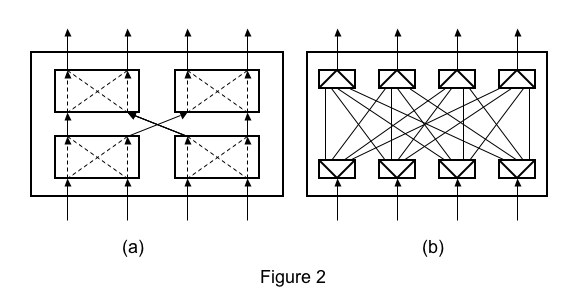
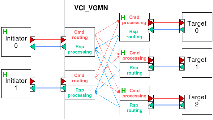
The VCI interconnect used for the TLM-T simulation is a generic simulation model, named VciVgmn. The two main parameters are the number of initiators, and the number of targets. In TLM-T simulation, we don't want to reproduce the cycle-accurate behavior of a particular interconnect. We only want to simulate the contention when several VCI intitiators try to reach the same VCI target. Therefore, the network is actually modeled as a cross-bar : In a physical network such as the multi-stage network described in Figure 2.a, conflicts can appear at any intermediate switch. In the VciVgmn network described in Figure 2.b, conflicts can only happen at the output ports. It is possible to model to specify a specific latency for each input/output couple. As in most physical interconnects, the general arbitration policy is round-robin.
E.1) Generic network modeling
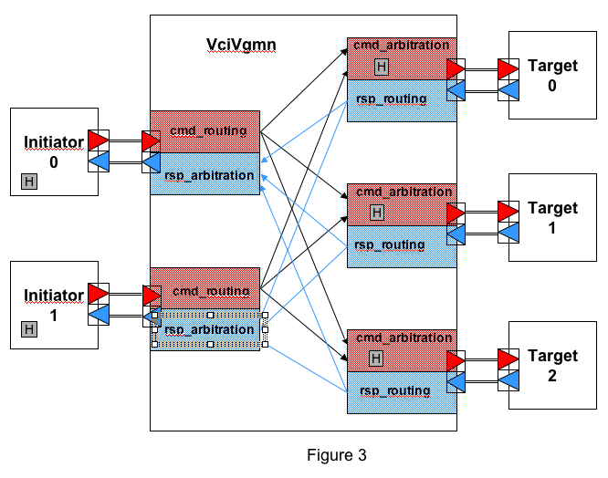
As in most physical network on chip, there is actually two fully independent networks for command packets and response packets. There is a routing function for each input port, and an arbitration function for each output port, but the two networks are not symmetrical :
- For the command network, the arbitration policy is distributed: there is one arbitration thread for each output port (i.e. one arbitration thread for each VCI target). Each arbitration thread is modeled by a SC_THREAD, and contain a local clock.
- For the response network, there is no conflicts, and there is no need for arbitration. Therefore, there is no thread (and no local time) in the response network that is implemented by simple function calls.
This is illustrated in Figure 3 for a network with 2 initiators and three targets :
E.2) VCI initiators and targets synchronisations
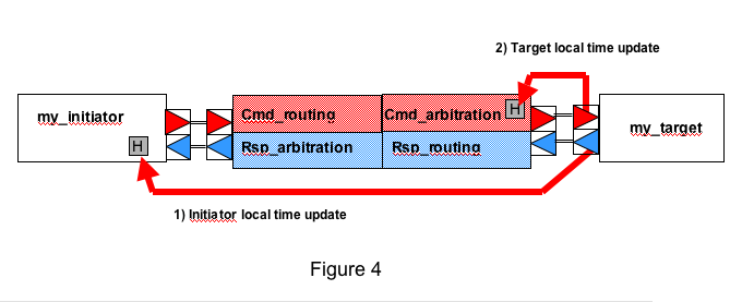
As described in sections B & C, each VCI initiator TLM-T module contains a thread and a local clock. But, in order to increase the TLM-T simulation speed, the VCI targets are generally described by reactive call-back functions. Therefore, there is no thread, and no local clock in the TLM-T module describing a VCI target. For a VCI target, the local clock is actually the clock associated to the corresponding arbitration thread contained in the VciVgmn module.
As described in Figure 4, when a VCI command packet - sent by the corresponding arbitration thread - is received by a VCI target, two synchronization mechanisms are activated :
- A VCI response packet with a date is sent to the source initiator, through the VciVgmn response network. The corresponding date can be used to update the initiator local clock.
- The cmdReceived() call-back function returns a date to the arbitration thread. This date is used to update the arbitration thread local time.
F) Interrupt modeling
Interrupts are asynchronous events that are not transported by the VCI network. As illustrated in Figure 5, each interrupt line is modeled by a specific point to point, uni-directional channel. It use two ports of type !'IrqOutPort and IrqinPort that must be declared as member variables of the source and destination modules respectively.
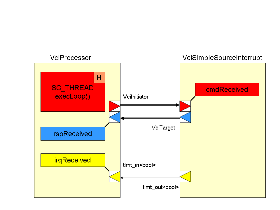
F.1) Source modeling
The source module (named my_source in this example) must contain a member variable p_irq of type IrqOutPort. To activate, or desactivate an interruption, the source module must use the irqSend() method, that is a member function of the IrqOutPort class. Those interrupt packets transport both a Boolean, and a date. The irqSend() prototype is defined as follows :
void  irqSend( bool  val,
            sc_time  time)
F.2) Destination modeling
The destination module (named here my_processor) must contain a member variable p_irq of type IrqInPortt, and a call-back function (named here irqReceived() that is executed when an interrupt packet is received on the p_irq port.
A link between the p_irq port and the call-back function mus be established by the port constructor in the constructor of the class my_processor :
p_irq(“irq”, this, &my_processor::irqReceived),
In the Parallel Discrete Event Simulation, the pessimistic approach suppose that any PDES process can update his local time only when he has received messages on all input ports with dates larger than his local time. Therefore, a SC_THREAD modeling the behavior of a module containing an IrqInPort should in principle wait a dated packet on this port before executing instruction and updating the local time. Such behavior would be very inefficient, and could create dead-lock situations.
The recommended policy for handling interrupts is the following:
- The call-back function irqReceived() sets the member variables m_irqpending and m_irqtime, when a interrupt packet is received on the p_irq port.
- The execLoop() thread must test the m_irqpending variable at each cycle (i.e. in each iteration of the infinite loop).
- If there is no interrupt pending, the thread continues execution. If an interrupt is pending, and the interrupt date is larger than the local time, the thread continues execution. If the interrupt date is equal or smaller than the local time, the interrupt is handled.
Such violation of the the pessimistic parallel simulation create a loss of accuracy on the interrupt handling date. This inaccuracy in the TLM-T simulation is acceptable, as interrupts are asynchronous events, and the timing error is bounded by the m_lookahead parameter.
F.3) Processor with interrupt example
class my_processor : Tlmt::BaseModule {
public:
    IrqInPort  		p_irq;

    // constructor
    my_processor (sc_module_name	name,
                  uint32_t  lookahead) :
    p_irq(“irq”, this, &my_initiator::irqReceived),
    m_time(0),
    BaseModule(name)
    {
    m_lookahed = lookahead;
    m_counter = 0;
    m_irqset = false;
    SC_THREAD(execLoop);
} // end constructor

private:
    tlmt_Time  m_time;  // local clock
    bool  m_irqset;  // pending interrupt request
    sc_time  m_irqtime;  // irq date
    uint32_t  m_counter;  // iteration counter
    uint32_t  m_lookahed;  // lookahead value

    // thread
    void execLoop()
    {
    while(1) {
        ...
        // test interrupts
        if (m_irqset && (m_irqtime <= m_time.getTime())) {
					// traitement interrupt
					}
				...
        // lookahead management
        m_counter++ ;
        if (m_counter >= m_lookahead) {
            m_counter = 0 ;
            wait(SC_ZERO_TIME) ;
            } // end if
        m_time.addtime(1) ;
        } // end while
    } // end execLoop()

// call-back function
     void  irqReceived(bool val, sc_time time)
    {
    m_irqset = val;
    m_irqtime = time;
    } // end irqReceived()
} // end class my_processor
Attachments (7)
- tlmt_figure_2.png (17.3 KB ) - added by 19 years ago.
- tlmt_figure_4.png (21.5 KB ) - added by 19 years ago.
- tlmt_figure_3.png (59.0 KB ) - added by 19 years ago.
- tlmt_figure_5.png (7.2 KB ) - added by 18 years ago.
- tlmt_figure_1.png (18.7 KB ) - added by 18 years ago.
- tlmt_vgmn.png (33.3 KB ) - added by 17 years ago.
- tlmt_initiator_target.png (10.2 KB ) - added by 17 years ago.
Download all attachments as: .zip
